Wednesday, December 1, 2010

Weeks 19 - 26


 Oops! Where did those promised 2 1/2 weeks go?  I failed my readers and will probably loose readership.  My bad.  Well, a lot happened and there just wasn't any time to tell about it or maybe it was just fatigue at the end of the daze.  Though there was some time for recreation as for example the Harvest Festival in the huge barnyard of the amazing Shelburne Farms.

The week prior to the move was devoted to installation of the linoleum flooring which required several stages of leveling the concrete floor where needed, cleaning the floor, letting the linoleum acclimate to the floor temperature, cutting the linoleum, bonding it to the floor, and filling the seams.  Although the linoleum product is fine the installation was less than perfect as promised by the second choice installer. I had my doubts about him when he said, " I may not be the cheapest but I'm good".  More on this in a post-natal discussion next year.

After the floor installation, the second coat of paint was applied to the walls, the major appliances were delivered and installed, the custom bar/bookshelf cabinet  was mostly completed, and the base boards attached.  Stairs were also added to all entrances.


I returned to Maryland on October 16 to start packing for the big move.  Packing  took a long time and couldn't have been finished without the help of friends Bob, neighbor Leonard, surprise helpers and old friends Betsy and Rob, and of course  workhorse Geoffrey and his able companion Ferdinand.  Sunday, Oct. 24 we left with most of the stuff stuffed carefully into a 26 ft truck that Geoffrey and companion drove.  A relaxing 12 hour drive at the end of a good weather week brought everything safely to Vermont.  The following day we had plenty of community help unpacking the truck in good time.


Since I've moved in I've spent a lot of time looking for and shoveling my stuff around trying to squeeze 2000 sqft of stuff into 800 sqft of living space.  Of course as that doesn't really work, much is left in the basement for winter enjoyment: sorting, culling, burning, etc.

After I moved, in the kitchen instant-on hot water heater and drinking water filter were installed.  Yet to happen is the installation of the wood stove.  In the interim I've constructed a cardboard model to get used to its location.  Though most walls have been decorated with pictures, the bookshelf in the living room has not been attached to the wall yet.  I also completed the shed door pulley system for the ramp door.


While all of this was going on, I also spent a lot of time helping Rick, Kelly, Thom, Jonathan, Joe, and many others from the community erect the yurt in its new location and wiring it with electrical outlets and switches.  Two of my couches, one light, and several chairs and a table were donated to furnish it.  Let the parties, the yoga mornings, the game nights, etc.  begin.

Down the street, the Habitat for Humanity houses are also nearing completion.  Though they don't look it they have a generous amount of foil-backed foam insulation: 10" under the basement slab, 6" in the walls with 6" of cellulose, 2 ft of cellulose under the roof and triple pane windows.

So now life in a new home has started.  In this time of Thanksgiving, I'd like to thank everyone in the community for  your tolerance of the work generated traffic and noise and for your help and comments of support.  My special thanks to Mary, who had given me much support during this time.  And of course much thanks to the building team of Tim Yandow, Dave, John and their many helpers and subcontractors.  It has been a wonderful experience.  I wish everyone joyous holidays and promise an assessment report in the New Year.

Monday, September 27, 2010

Weeks 17 & 18


This may be the last posting before the final one, upon completion, now estimated to be in two and a half weeks.  Not much has been happening outside except for the start of some entry stair construction and the sealing of the natural pine ceilings of the solarium and the entry way.  Inside, however there has been much activity related to door installation and door and window trimming.  A first coat of paint has been applied by spray gun and the cabinets have started to be hung.  The cabinet appearance is funky because there was no attempt made to match adjacent pieces as to shade and structure.  It looks like a Cubist work of art - the glass is half full.

The electricity has been turned on and the electrical heat is working, currently being used to help dry out the concrete floor.  The picture shows electrician Steve, plumber, Randy and electrician Nick.  In the background you can see.......the 10 kW heater, expansion tank, and pump.  Not visible are the manifolds for the three zones (bedroom, main, and half of basement), the zone valves, the low water detector to protect the heater and many ball valves and faucets for maintenance.


The Yurt Hunt
Last week I participated in a Yurt hunt, that is to say, we went to Red Hook, NY and disassembled a 5 year old, 24 ft. diameter Pacific Yurt and hauled it back to our community to serve as an interim "Common House".  Although it was tricky disassembling the yurt, most of the work was disassembling the deck supporting it.  Yurts are great for milder climates and not too easily adaptable to colder, windy climates so we may have a few weeks where it just won't be worth trying to heat it.  With walls that are leaky and only have maybe an R5 insulation, the pellet stove will have to work hard on those windy below zero evenings.

The Solar Energy Collector Choices
In the last post it was estimated that without wood heat that I would use at minimum 6700 kWh of energy per year after subtracting the passive solar contribution.  So how can we capture that much energy with active solar?  

Many say that solar thermal is the best way to capture solar energy in the form of heated water.  But what is the complexity of a solar hot water system and how well does it perform?  Many also say that solar photovoltaic is inefficient and too expensive.  Let's look at the numbers for residential systems.

For both types of collectors, it should be noted that they are rated for the sun at full intensity shining at normal incidence, i.e. perpendicular to the collector surface.  Any deviation in angle from normal will lead to a greater proportion of the sun's energy being reflected from the transparent/translucent glass surface which protects the collector.  Thus fixed collectors cannot be as efficient as single or double axis sun tracking collectors.  Up to around 40% of potential sun energy is lost due to reflection experienced by fixed collectors.

A solar thermal system usually consists of one or more black body collectors which heat water.  When the water reaches a temperature greater than the destination temperature, a pump transfers the heated water, in most cases through a heat exchanger at the bottom of a large water tank.  A heat exchanger at the top of the tank can be used to supply heat from a backup source, be it electric or gas.  The heated water in the tank can be used for either washing or heating a floor.  A simple system consisting of one collector, tank, pump, differential temperature control and plumbing can cost in excess of $6K, I was told by one supplier.  Long periods of cold and overcast skies will require a backup heat source, yet possibly an extra expense.  Panel efficiencies are usually around  70% at normal incidence for either flat panel or solar tube collectors.   Considering that they are not pointing toward the sun at all times during the day, they are only receiving around 60% of the potential energy they could receive thus giving them in reality around 45% efficiency.

A solar photovoltaic system usually consists of one or more PV panels mounted either fixed on a roof   at an optimal angle or on a sun tracker.  The direct current (DC) produced can then be stored in costly batteries for off-grid usage or be changed to alternating current (AC) by an inverter for connecting to the grid and thus using the grid as a bank account.  This assumes that one is allowed to tie in by the local utility and assumes that the utility pays a reasonable rate for electricity received.  Installation of fixed panels on properly oriented roofs requires penetration of the roof's surface for the panel mounts and the wiring.  Other considerations for roof mounted systems are leaf debris and snow accumulation on either side of the panels and the beneficial heating of the roof in the winter months.  Trackers are complete systems that can be easily inserted into rigid soils with a small front loader.  Trackers are more complex mechanical and electrical systems with some using GPS for tracking and cell phone connections for monitoring and on-line reporting of performance.  A 4 kW tracker will have 20 solar panels, each capable now of operating at its maximum efficiency which may be around 17%.

Purchasing alternative energy equipment is currently supported by rebates and tax credits, not unlike the estimated over $500 billion support of fossil fuels worldwide (Where is this free market?).  For example, a 4000 W system, capable of generating around 5640 kWh annually in Vermont would cost $31,000.  After a $4000 rebate from the Vermont Renewable Energy Resource Center and a 30% federal tax credit, the final cost is $17,700 installed.

In the co-housing community in which I am building there is the opportunity to place the collector in the lower more wind-protected, yet wide open meadows rather than in the tight residential area.  This my plan and it will be appreciated by the sheep grazing there as they are always seeking shade in summer.  Now where is that pot of gold the rainbow last week was pointing to?


And finally a whazzit puzzle found around the construction site:

Saturday, September 11, 2010

Weeks 15&16

Since there wasn't that much to report or document on the house in pictures, I thought I would start off with an evening at Charlotte Beach, the picture symbolizing the near completion of this building adventure.

The errant windows arrived and were quickly installed enabling the completion of the siding attachment.  Inside the wall board or dry wall hanging was finished one week and the plastering was finished the following week, being executed by a real artist.  The stove pipe was also installed with the help of Balky, the lift, that had been behaving since it obtained a new joystick.  The "parging" of the part of the basement wall protruding the soil was started.  This process consists of adhering multiple layers of various materials to the insulating foam surface to result in a weather resistant cover.


 The Habitat for Humanity House


I had mentioned some posts back that Habitat for Humanity has been building two houses down the road that are designed to meet the Passive House energy standard.  The first house is a conventionally constructed one whereas the second one is prefabricated.  As with all their houses, much donated material and labor goes toward their completion.  These houses are being built under the guidance of Project Directors Peter Schneider from Efficiency Vermont and Architect John Clancy.

This design does not have much thermal mass but relies on much insulation to stem heat flow.  Observed under the basement slab was 10" of "blue board" foam insulation .  The walls are conventional 2" x 6" construction with 6" of foil-faced TUFF-R isocyanurate foam boards on the outside and cellulose insulation on the inside.  The roof has a truss construction that will allow around 30 in. of cellulose insulation. The goal is to have R100 in the roof and the basement with around R80 in the walls - if I remember correctly.  The windows are triple pane from Thermotech.  There is no website yet detailing this project even though the designs are being evaluated as standard future designs for colder climates.  The recipient of one of the houses, however,  is keeping a blog.

The house will be more conventional in appearance than my house and definitely more livable for a family of four.

More Energy Discussion
Did I mention last time that my low ball estimated energy consumption of 6700 kWh is only 84 kWh/m2-hr which is 30% better than that vaunted German Passiv Haus standard.  Of course, I've not accounted for some of the heat losses yet, so for now this is only numbers in cyberspace not real life living in my Haus.  Tune in on the real story next year.

This week we will see how the total heat cost will be "covered'.  By covered I mean how will the estimated annual need of 6700 kWh heat be produced?  Options around here are propane gas, electricity, wood, coal, or oil.  I've already said that I'd like to use as little fossil fuel as possible which eliminates propane, oil, and coal, leaving wood and electricity.  Of course we all realize that wood needs to be cut, transported, chopped, and delivered which right now is done with oil powered equipment.  Electricity in our area of Vermont comes largely from two sources, 47% hydroelectric, mostly  from Quebec Hydro, Canada, and 42% nuclear from Vermont Yankee which may be or maybe not be shut down soon depending on which way this political football bounces.  My intention is to try to minimize electric use by producing much of it myself with solar PV arrays and use wood as backup heat for the colder periods of the year and for power outages, though they have been rare.

Wood heat isn't cheap if you add the cost of a chimney and a nice stove to the cost of the fuel.  My Bari stove can generate from 12K-30K BTU/hr. which is much more than my hourly needs of 9520 BTU/hr on a zero degF (-18 degC) day.  Because the stove has a soapstone liner which gives it around 50 BTU/degF thermal mass, it should be able to moderate its heat output a little and hopefully the thermal mass of the inside of the house estimated to be greater than 15000 BTU/degF should be able to further moderate the emitted heat from the stove for short burns as it will take about an hour of burning to raise the temperature 1 degF... approximately.  After the stove no longer emits heat it should take about two hours to see a 1 degF temperature decrease .... approximately.

So how much energy can one get from a pound of wood?  In the laboratory one can get about 8600 BTU/lb.  After subtracting the energy required to vaporize the water content (20%)and taking the burning efficiency of the stove into account, maybe half that amount of energy can be recovered.

All wood, regardless of species, has about the same energy per pound.  The different species vary only in density.  A cord (128 sqft) of white oak wood  for example has about 30 MBTU (approximately 8800 kWh) which would more than cover my annual expected usage of 6700 kWh. Thus as a backup heat source, a half cord/yr may be enough.

Next time we'll look at the solar energy options for fossil free energy.

Please send me comments that add to the discussion and correct any errors of comprehension.

Wednesday, September 1, 2010

Week 14

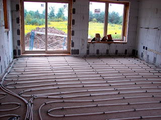
This was the week of the last concrete pour and the last concrete patty of about 8 left by the pumper and concrete delivery trucks for later disposal. 


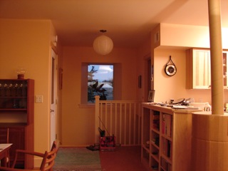
The water supply rough plumbing on the first floor was also completed.  The first floor is now ready for the wall board installation next week to cover everything except the windows and doors. 


We even received the stairs to the basement which came in two sections that were quickly installed and had walls framed around them. 


Outside, the trim, siding, shingles,  gable vent,  and attic entry door were completed on the west side.  This was achieved with the help of Balky, a Genie Boom rental lift that had to be pampered just right to do any lifting.


The Cost of Heating

In week 4 we stated the basic energy need equation, En = EL - EG.  The energy needed, EN, to heat the house to a desired temperature T is the total energy lost, EL, to the outside minus the total energy gained, EG, by internal activity and solar heat gain. We defined the desired temperature at 68 degF.

In week 13 we estimated the solar gain contribution of the windows which on an annual basis is 2370 kwh, not counting June, July, and August contributions as they are too much to meet the heating need and need to be blocked.  One other gain previously discussed is the occupant generated heat, around 2.4 kWh/day-person which for one person is 876 kWh/yr.

Several weeks back we determined that the house is estimated to use around 140 BTU/degF. Using this number and combining it with the Vermont average monthly weather data we arrive at an annual need of 6500 kWh after a 2370 kWh passive solar contribution. Other heat losses are from the heat recovery ventilator, uncontrolled air leakage, ingress and egress activities, and water usage losses. 

Heat Recovery Ventilators are needed for air tight houses during heating days to avoid humidity and CO2 build up.  These units will draw in fresh outside air and heat it from the heat of the stale inside air which is expelled to the outside.  This occurs in a two chambered non-mixing polypropylene heat exchanger.  There are various ventilation standards with the Minnesota standard requiring .05 CFM/sqft + 15 CFM/person which would be 55 cubic feet/min for this house with one occupant. 
The chosen ventilator is a Venmar Constructo 1.0  which is rated at 45-96 CFM with an efficiency of 76%  at a 70 degF difference between the inside and outside air and 50 CFM.  According to the data sheet, which is not very specific, at 32 degF external and 50 CFM, 44 W of electricity are consumed.  If this ventilator were to run all the time it would annually consume almost 400 kWh just to move the air.  Judging from the two motor design layout, about half the motor heat will be exhausted to the outside, the other half will go to heat the incoming air .  It is unclear how much energy is consumed by the defrost cycling which occurs below 23 degF.

The ventilator would most likely not be used during the warmer months as the windows would then be used for ventilation and temperature control instead.  For the 264 days of usage (Sept.-May), the average outside air temperature is 38 deg. Assuming this air to be at 50% humidity, heating it to 68 degF would take 15 KBTU/day as can be determined from a psychometric chart and assuming that 2/3 of that heat can be recovered from the exhaust air.  For the heating season this would compute to an annual consumption of  1160 kWh.  Using it at less than 50% would half this to say 580 kWh/yr. Adjusting the motor heat consumption for the heating days and the 50% duty cycle of operation, would subtract 74 kWh/yr for a final 500 kWh/yr heat need.  (Disclosure: I am not a thermodynamicist just an electrical engineer who had to take thermodynamics almost a half century ago)

All water entering the house enters estimated at 50 degF.  It will most likely exit at the house temperature of 68 degF.  Thus for an estimated daily usage of around 100 l (25 gal) this represents a heat loss of around 600 kWh annually.

Uncontrolled air leakage losses are a function of the tightness of the house construction, the temperature difference of the inside and outside air, and the external wind pressure.  I will assume this to be zero currently and will wait until it can be measured with a blower door test to be performed by Efficiency Vermont.

Ingress and egress losses are a function of the life style and habits of the house occupants.  Every time a door is opened during the heating season a certain amount of heat is lost in the air escaping and a certain amount of heat is needed to heat the person's belongings and clothing from the outside temperature to the inside temperature.  This is assumed to be zero for now and will be measured later.

We thus have optimistically, the following heat needs in kWh:
En = conductive losses + HRV losses + water losses + uncontrolled heat losses + ingress/egress losses - solar gain - occupant heat
En = 8855 + 500 + 600 + 0 + 0 - 2372 - 876 = 6700 kWh
Thus at the 0.15cents /kWh expected later this year, the heat need would cost 1000 $/yr.  The only other electricity costs not covered by this would be external lights (1) and the HRV motor heat loss of 74 kWh/yr.

Next time we'll see whether this is good and how this cost is covered - or not.

Please send me comments that add to the discussion and correct any errors of comprehension.

Monday, August 23, 2010

Week 13

Week 13 unfortunately missed the only Friday the 13th (my lucky day) this year by one week.  But I digress.  This week, much external trim work was  completed except under the gables. Placement of the siding commenced.


The brackets for the entrance portico were also attached and the ceiling of the portico was covered with pine planking similar to the solarium.  (This is a portico without columns). Gable shingles yet to come.


Inside, the channels for the electrical lines carved into the ICFs were filled with expandable polyurethane foam.  Nail plates were placed at 18 in. intervals along the top and bottom of the walls to allow for easy fastening of  trim and baseboards.

The radiant floor hot water tubing was attached to the floor in preparation for the concrete pouring of the floors next week.  The 1/2 in. (inner diameter) PEX tubing is looped at intervals of 9". There are three control zones: the living room,  kitchen, entry way, and bathroom room area (900 ft), the bedroom (300 ft), and the basement (600 ft). The living room and basement have two loops/per zone.  There is also about 380 ft of tubing placed next to one of the living room loops which is to serve as a small volumetric capacity (7 gal) preheater of washing water for the instant-on water heaters.

More Realistic Solar Heat Gain
Using the US Solar Radiation Resource Maps, based on solar radiation data gathered from 1961-1990, one can compile the average solar energy impinging for a year on a flat surface here in Vermont.  The graph below shows this energy density in kWh/m2-day, Jan - Dec, under the following conditions:
Series 1 : 30 year average daily energy density falling on a vertical surface pointing south
Series 2 : minimum average daily energy density on above surface during the 30 year interval
Series 3 : 30 year average daily energy density falling on a south facing surface tilted at latitude
Series 4 : As in Series 3 with East West single axis tracking.

Since these curves are functions of cloudy days and sun position in the sky throughout the year a few observations can be made from these graphs. The summer dip in Series 1 is mainly due to the high sun angle in summer. One would expect a dip also in winter partially due to shorter days and this can be seen in Nov. and Dec. but not in Jan. and Feb. because of sunnier days than in Nov. and Dec.  The Series 2 curve shows that there can be some very cloudy months throughout the year on occasion. Series 1 and 2 are for vertical panels such as widows.  Series 3 and 4 are for panels tilted at latitude (44.3deg, which is very close to the roof angle), i.e. for roof-mounted solar thermal or photovoltaic collectors.  Series 3 is for a roof-mounted panel and shows a flattening during the summer as the sun actually rises above the latitude angle by almost 25 degrees.  Series 4 shows the advantage of east-west tracking.  No data was taken for 2-axis tracking which should further broaden the area under the Series 4 curve.

Translating these data to practical terms, we can say that except for the dark and cloudy Nov. and Dec. months we can expect to have around 30K BTU penetrate the south facing windows daily.  This is assuming full illumination which isn't quite the case as except for the western most south facing windows the others are partially shaded in the afternoon by the walls to their west protruding to the south. So let's say, for further discussion, there's only a 20K BTU gain per day.

Next time we'll look at total thermal gains and losses and estimated yearly energy cost if the only heat source other than solar is electric.  We'll also look at the influence of the thermal mass on the temperature regulation.

Please send me comments that add to the discussion and correct any errors of comprehension.

Wednesday, August 18, 2010

Week 12

Installation of all delivered windows and external doors was completed.  An adhesive backed tape is placed over the outside of the window bucks to the outside foam as a water guard against any rain driven penetrations. Much shimming and leveling is necessary to mount the windows and doors straight in their rough opening.  The remaining gaps are filled in with expandable foam, casting the windows in place and creating a well-sealed and insulated space surrounding the window frame.  The green water impermeable membrane was used to cover the wood portion of the window bucks that had angled internal sides.


The wallboard guys breezed in and out and within what seemed like an hour had the ceiling boards in place.  This ceiling board had a water impermeable aluminum layer on one side to prevent humidity from the living space from penetrating into the cold attic.

A visit by an energy inspector from Efficiency Vermont to inspect the house for Energy Star Rating, pointed out that one of the biggest leaks of energy out of the living space into the attic takes place at the interface of the ceiling board and internal walls.  (European readers may wonder how this could be as they may not realize that we have a tradition of building hollow walls out of 2" x 4" "studs" or more precisely by 1.5 in x 3.5 in wide lengths of lumber).  These hollow walls may have electrical wire or plumbing holes in them which allow air entering the wall from the attic to leak into the living space or vice versa.  Traditionally, these houses were said to "breathe well".  But to build to new standards, these gaps as well as all wall penetrations into the roof need to be sealed with a flexible caulk for air tight construction.

Miss Inspector took pictures of every glass penetration of the outside walls, as these contained the U-vale and SHGC numbers for heat loss/gain calculations.  She was happy with the fresh air supply for the wood stove as now required by Vermont law.  The solarium air preheat ability for the HRV supply air was also appreciated but she was concerned about possible blockage of inlet air by the solarium design.  The use of a  Heat Recovery Ventilator is a requirement for air tight houses to maintain proper humidity and oxygen levels.  These units inhale fresh outside air, exhale stale inside air, and recover most of the energy in the exhausting  air by using it to heat the inhaled air in an isolated aluminum cross-flow chamber.  This device is clearly still a source of heat loss, however with a perfectly tight house design, the air heat loss can be controlled by the HRV's frequency of operation.

Miss Inspector took issue with my plan to electrically heat my house, with wood heat backup for electrical power outages and extra cold days.  She conceded that Propane heat is nearly as expensive as electricity and is also not considered a future energy source.  She suggested more usage of the wood stove though I had to inform her of the smoke concern in the community.  She said that the electrical utility is concerned with excessive demand.  I wondered if she had the same concern about the demand placed on the utility by the mega-mansions going up around some parts here as she had about the minimal estimated demand of a small energy tight house.  She looked at her watch and had to suddenly leave for another meeting in her fancy crossover vehicle......

Speaking of wood stoves, I had a difficult time making up my mind on a suitable wood stove for backup heating in case of power failure, extreme cold, or romantic setting needs.  Initially I looked at a Danish made RAIS stove, however, the price tag for the stove itself plus the expensive stove pipe installation coupled with an inflexibility in installing the stove pipe in a timely fashion made me shop around at a much closer store overlooked before.  Bingo! They had a better stove for the same amount of money and they were very accommodating to our schedule needs.  The stove is from a German Company, Hase and it is the Bari model.


Window Heat Gain
In week 9 we looked at the heat requirement of the windowless house and found that at 32 degF 2800 BTU/hr would be required to keep it at a comfortable 68 degF.  In week 10 we looked at the solar energy or insolation (BTU/sqft-day), available in this part of Vermont. Today we will look at the many factors affecting passive heat gain from windows in the house.  We will not consider the reduced heat loss through the warmer walls on sunny days.

In week 11 we detailed four parameters for all of the "windows" or more precisely for all of the window and door penetrations of the house wall.  The rough opening (RO) defines the area of wall penetrated.  The U value is the parameter that defines the averaged heat loss through the complete window opening including the frame, sash, and any hardware (usually metal) for opening and closing the windows.  The SHGC  gives the percentage of normally incident solar energy falling on the complete window that actually manages to penetrate to the inside.  Non-glazed portions of the window and glazing losses such as reflection and solar heating of the glass will reduce this number.

To obtain the total heat loss due to the windows and doors of the first floor we just sum their UxRO products from week 11.  Doing this we arrive at 67.7BTU/hr-degF  which points out when compared to the heat loss of the walls, floor, and ceiling (72 BTU/hr-degF), that the windows are 48% of the heat loss at night.  This clearly shows that good shutters should clearly reduce night time heat loss.  Of course, the windows are also the main heat gain during the day, especially on cloudless days.

The north facing window will only see diffuse light most of the year with some north light at low incidence in summer.  The east and west windows will see nearly direct incidence light mostly in summer which is nice in the morning but may lead to too much heat later in the day.  Since there will be no active cooling (AC), inside summer temperatures will be modulated by opening windows during the cooler nights and closing them during the day when necessary.  Window shades will assist in diminishing the western sun. Having said all of the above, only the heating season needs will be addressed with only the south facing windows assumed to have solar gain.

To help us estimate the maximum amount of heat gained by the south facing window we first sum up their glazing area x SHGC products.  Doing this we arrive at 26.5 sqft.  Now, were direct sunlight to shine onto all windows at normal incidence on a clear day, we could capture around 8000 BTU/hr, considering that solar energy is optimistically around 300 BTU/hr-sqft at noon.  But as that isn't ever the case  for vertically mounted windows, we must subtract the reflected light which will vary as the sun travels on its path across the sky.  Our tax supported government offers for free a solar position and intensity calculator which shows all the factors involved in arriving at actual values of insolation for any place on earth.  Furthermore, our government provides for free, maps that show the energy incident on various types of fixed and tracking collectors for any period of the year, based on historical data. From this we can obtain, for example, monthly passive heat gains for vertical unobstructed south-facing windows. We can then compare that heat gain to the actual heating requirement for maintaining the house at 68 degF.   That is a task for the next posting.


Please send me comments that add to the discussion and correct any errors of comprehension.

Friday, August 13, 2010

Week 11

Other than Comcast canceling my email account and Gmail suddenly not recognizing me as an author of any blogs because of an association with my cancelled Comcast email account, it's been a good week.  Thus this somewhat late and new continuation blog.  Now for the real progress.

The main roof was completed this week including the roofs over the entrance portico and the shed.  A heavy downpour validated a good job was done.  Externally, corner trim boards and vertical strapping boards were attached in preparation for siding attachment.  Between the strapping a densely fibrous, yet porous material was added to prevent insects from creating habitats under the siding, yet allow air circulation to aid in moisture build-up prevention after heavy wind-driven rains. (This 1/2" air layer together with the siding adds almost another 2 to the R value of the walls making them R40).  


More strapping was also added in the ceiling to avoid the weight of the blown-in insulation from deforming the ceiling boards.  In preparation for the ceiling board installation an insulated stove pipe collar was placed in hopefully the correct position.

The windows and glass doors arrived from Inline and as expected perfection in ordering was not achieved.  Two of the windows had the wrong size entered in the quote and even though the error had been communicated it propagated through to production and two of the windows were too long vertically by a foot and unacceptable considering that they would be showing the back of furniture and potty-goers sitting on the toilet.  This experience has taught a lesson of identifying each window uniquely on the drawing and on the factory order and that the builder should verify each window specification on a copy of the production order which was not supplied.  Another lesson learned is not to use one manufacturer's standard size numbers for specifying window sizes for another manufacturer who has no standard sizes and has total flexibility in window size construction.

The windows all have fiberglass frames with a dark bronze color externally and a almond color internally.  All north windows are triple pane and fixed with the exception of one which was shipped as a casement window when it was also to be fixed, another product of communication and execution errors.  This error was somewhat reluctantly accepted.  All other windows are double pane. 

Window Data Stuff
(Remember that a part of this blog is personal documentation ).
The following locates the various windows and doors in the house and gives the data in parenthesis for each item (Uvalue, SHGC, glazed area, rough opening area).  The U value is BTU/hr-sqft and the areas are in sqft.  These data will be used later to compute the heat gain and loss due to the various components. 
The bedroom has one fixed north facing window (0.17, 0.3, 3.07, 5.51), one east facing awning window (0.30, 0.29, 3.19, 5.65) and two south facing double hung windows (0.32, 0.33, 19.7, 30.4).  The bathroom has only one fixed north facing window (0.17, 0.3 , 3.07, 5.51).  The kitchen has one east facing tilt and turn door (0.33, 0.26, 9.39, 19.3) which goes to the solarium and two south facing fixed windows (0.26, 0.33, 20.9, 28.9).  The living room has one east facing fixed window(0.26, 0.33, 5.67, 8.84), one south facing sliding glass door (0.29, 0.21, 29.5, 42.4), and two south facing fixed windows (0.26, 0.33, 20.9, 28.6).  On the west side there are two casement windows (0.30, 0.29, 15, 16.7) which have angled vertical sides to help distribute the light better through the thick wall openings.  The window on the north side is fixed (0.17, 0.3, 8.64, 10.9) and has similar angled sides.  The mudroom has one north facing casement window (0.21, 0.25, 7.5, 10.9) and one half-glazed entry door (0.18, 0.13, 5.12, 24).  The exit door from the mudroom into the living space is also an entry type door also half-glazed but it doesn't sit in the outside wall.  It provides some extra insulation between the mudroom and the living space.  These two doors, from Therma Tru) are meant to be more community friendly and less isolating.

The total wall penetration area for windows and doors is 254 sqft or 25%.  Total glazing area is 167 sqft or only around 2/3 of the wall penetration area.  The south side has 9%, the north 2.2%, the east 1.8%, and the west side 3.5% of the glazing.

Because of a personally busy week, geek moment will continue next week - maybe.